networking
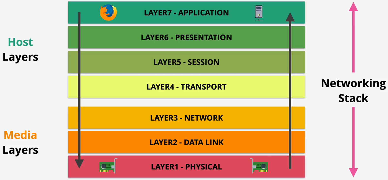
OSI Model
Components
- Local networking - Ethernet
- Routing
- Segmenting, ports and sessions
- Applications
Key features
- Higher layer built on lower layer, adding features and capabilities
- This bottom-up approach illustrates the limitations of each lower layer and how each subsequent upper layer was developed to address and overcome those limitations
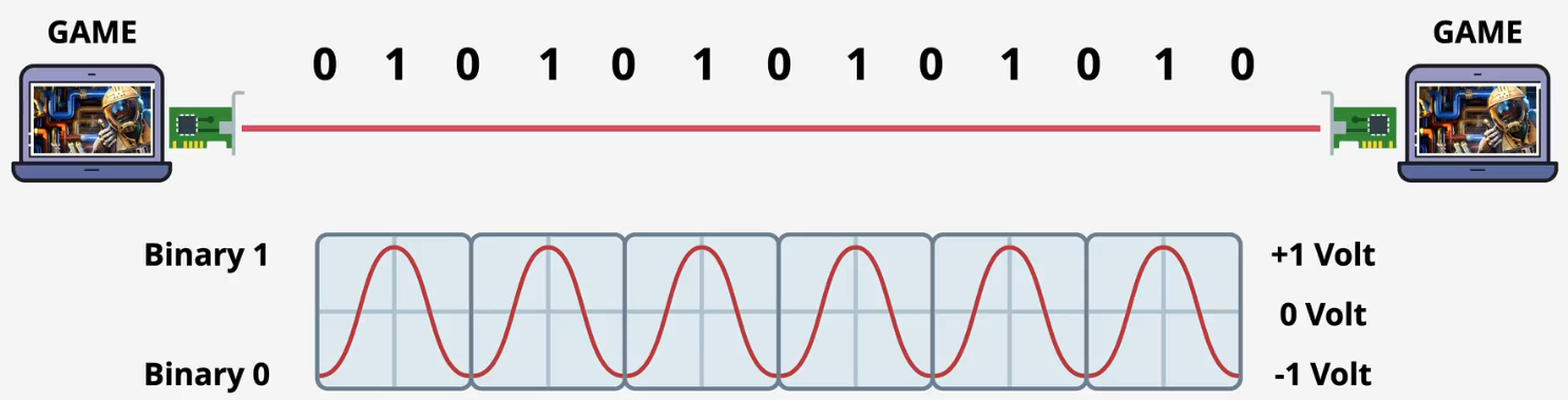
Layer 1 - Physical - Bit
Key features
- Layer 1 (Physical) specifications define the transmission and reception of raw bit streams between a device and a shared physical medium
- It defines things like voltage levels, timing, rates, distances, modulation, and connectors
- Physical medium can be copper (electrical), fibre (light), or wifi (RF)
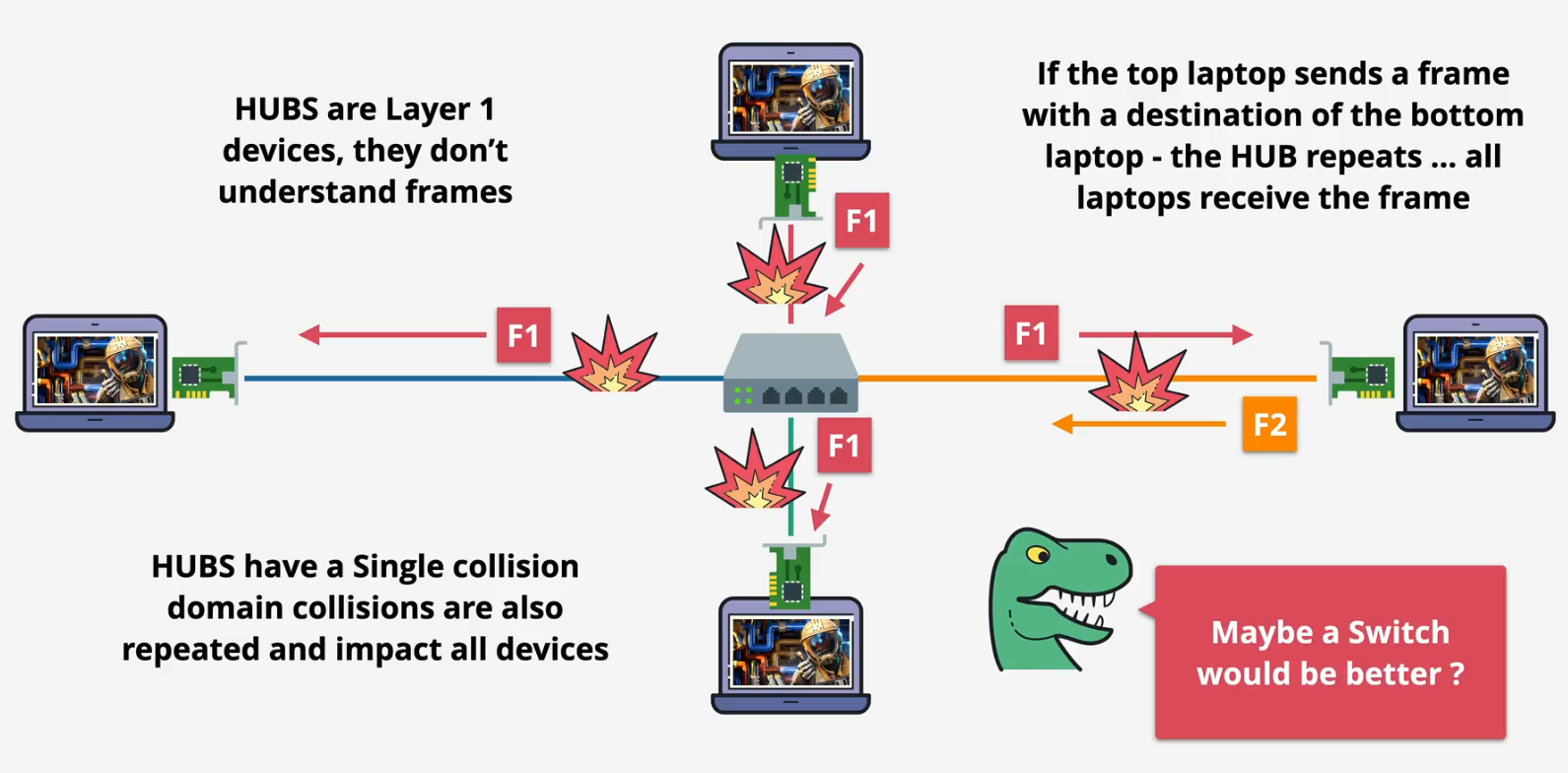
Physical HUB
- Connects two more devices
Combinations
- We can mix and match multiple components depending on the network's needs
- Cables and NICs
- Cables and transceivers
- Cables and repeaters and hubs
- Cables and wireless access points
Summary
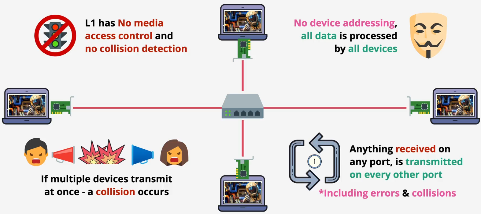
- Physical shared medium
- Standards for transmitting onto the medium
- Standards for receiving from the medium
- No access control
- No uniquely identified devices
- No devices → Device communications
Layer 2 - Data Link - Frame
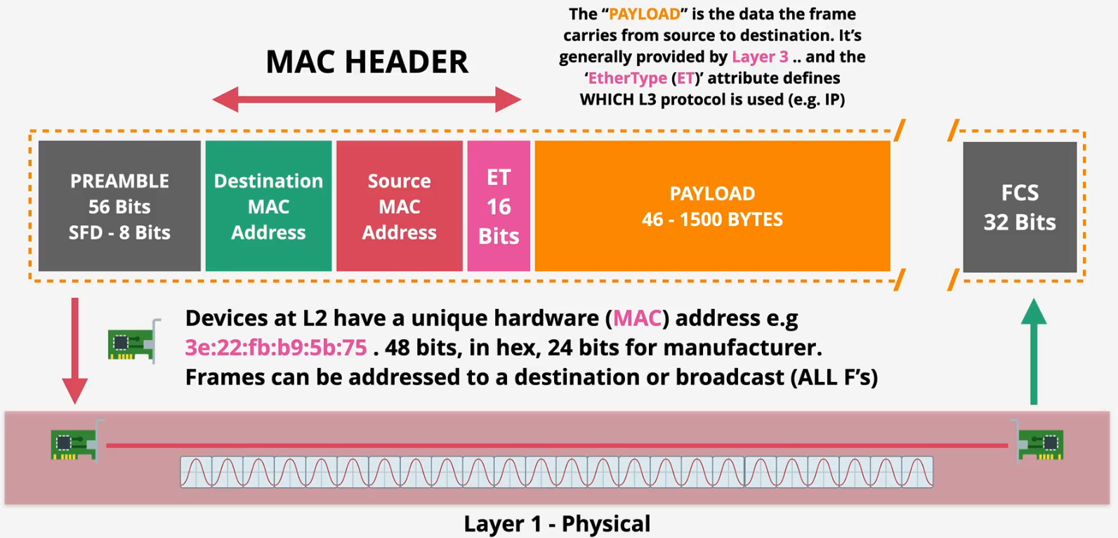
Components on frame
- Preamble and SFD: Define the start of the frame
- MAC header: Contains the destination and source MAC addresses and the EtherType field (layer 3 protocol)
- Payload: The data encapsulated within the frame
- FCS: Check to detect any transmission errors
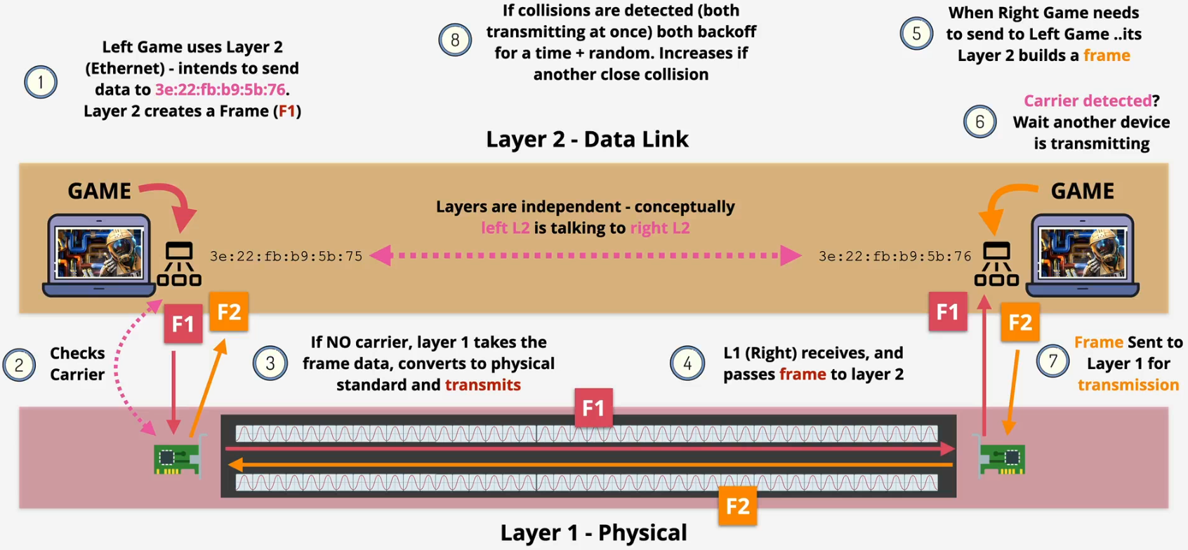
CSMA/CD - Carrier-sense Multiple Access/Collision Detection
- Challenge
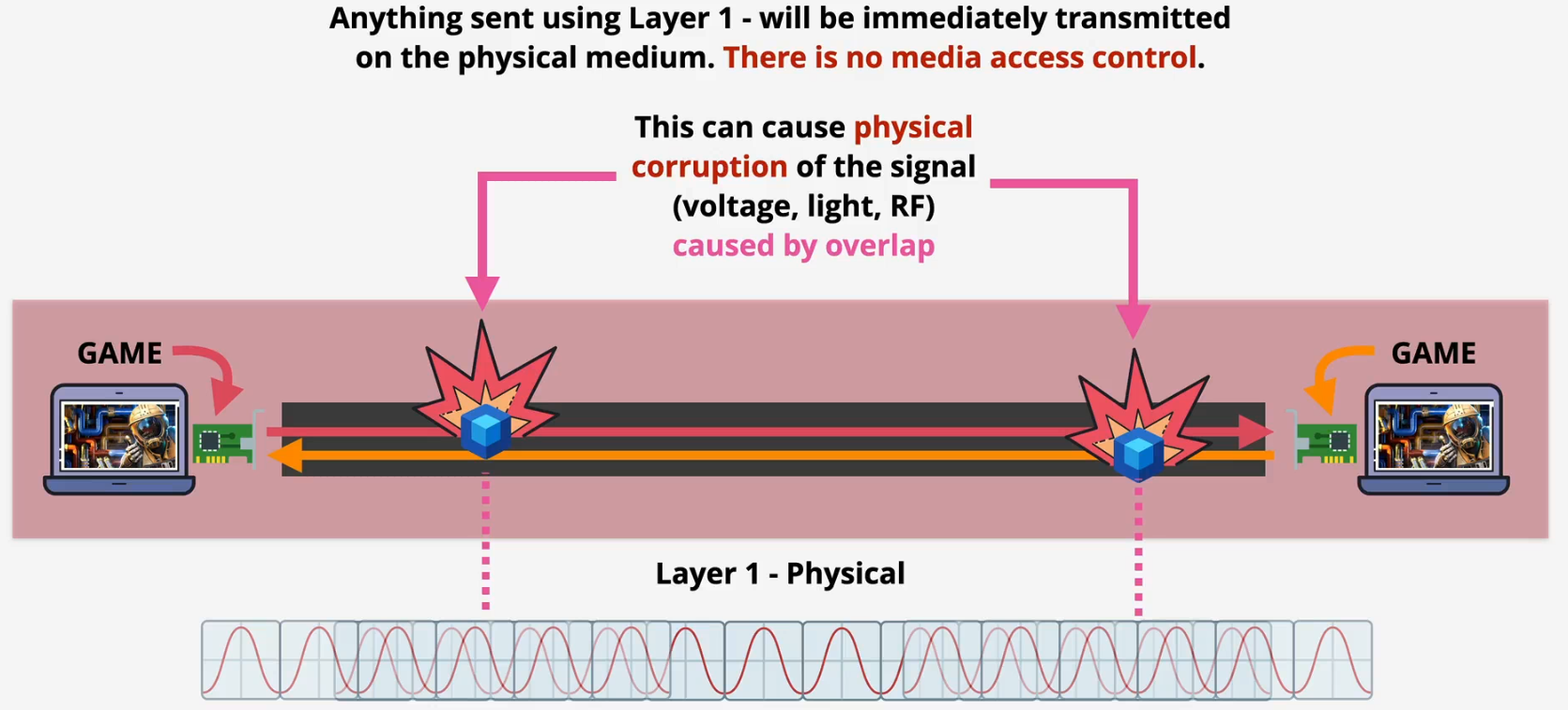
- Solution
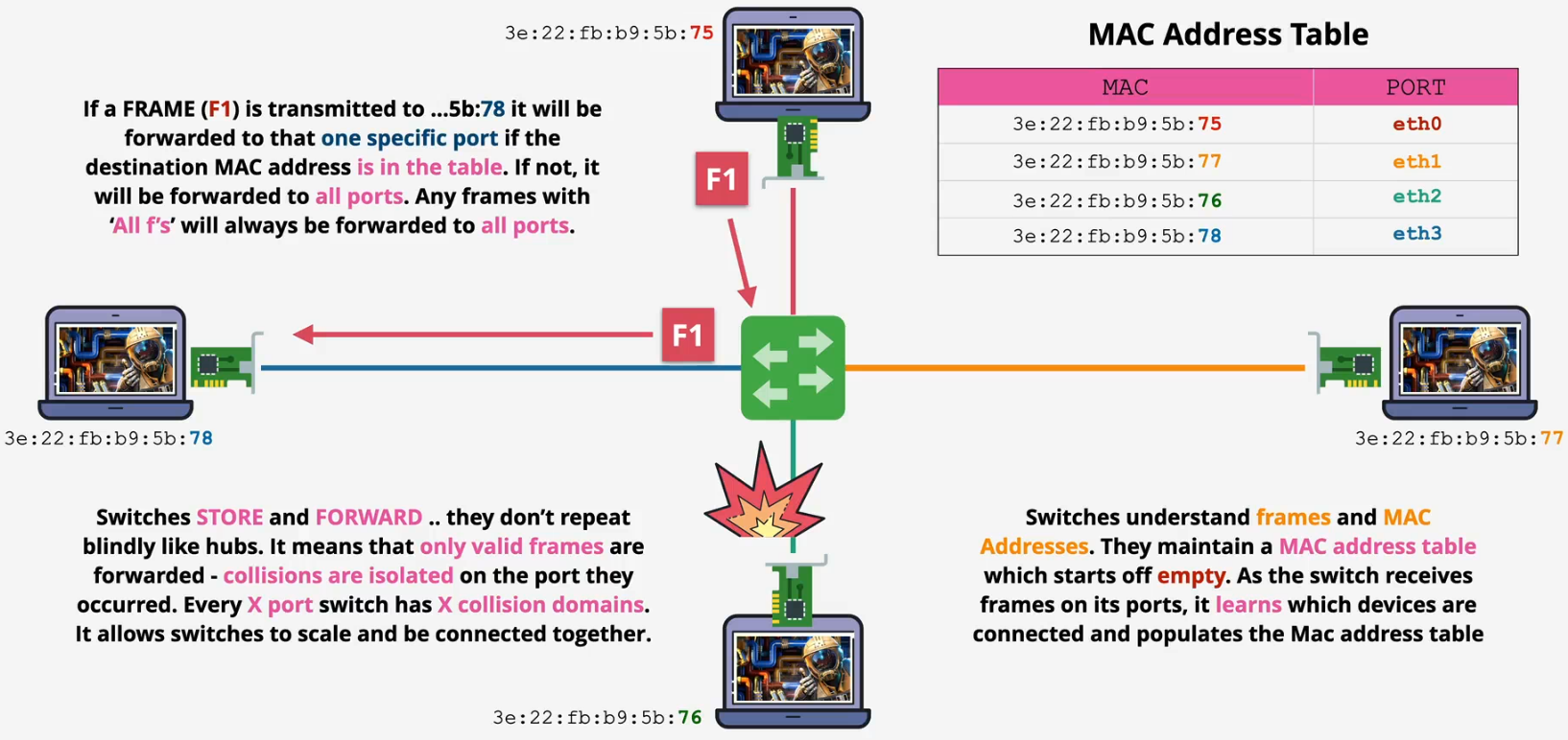
Switch - Layer 2 device
- The NIC handles the conversion of a structured frame (Layer 2) into raw bits encoded as physical signals (Layer 1) for transmission
- Problem
- Solution
Summary
- Identifiable devices
- Media access control (sharing)
- Collision detection
- Unicast 1:1
- Broadcast 1:ALL
- Switches - Like Hubs with Super powers (Layer 2)
Layer 3 - Network - Packet
Decimal and binary
- Human vs. computer
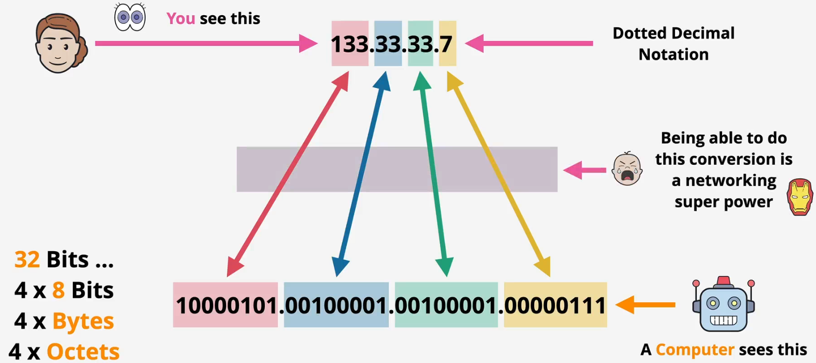
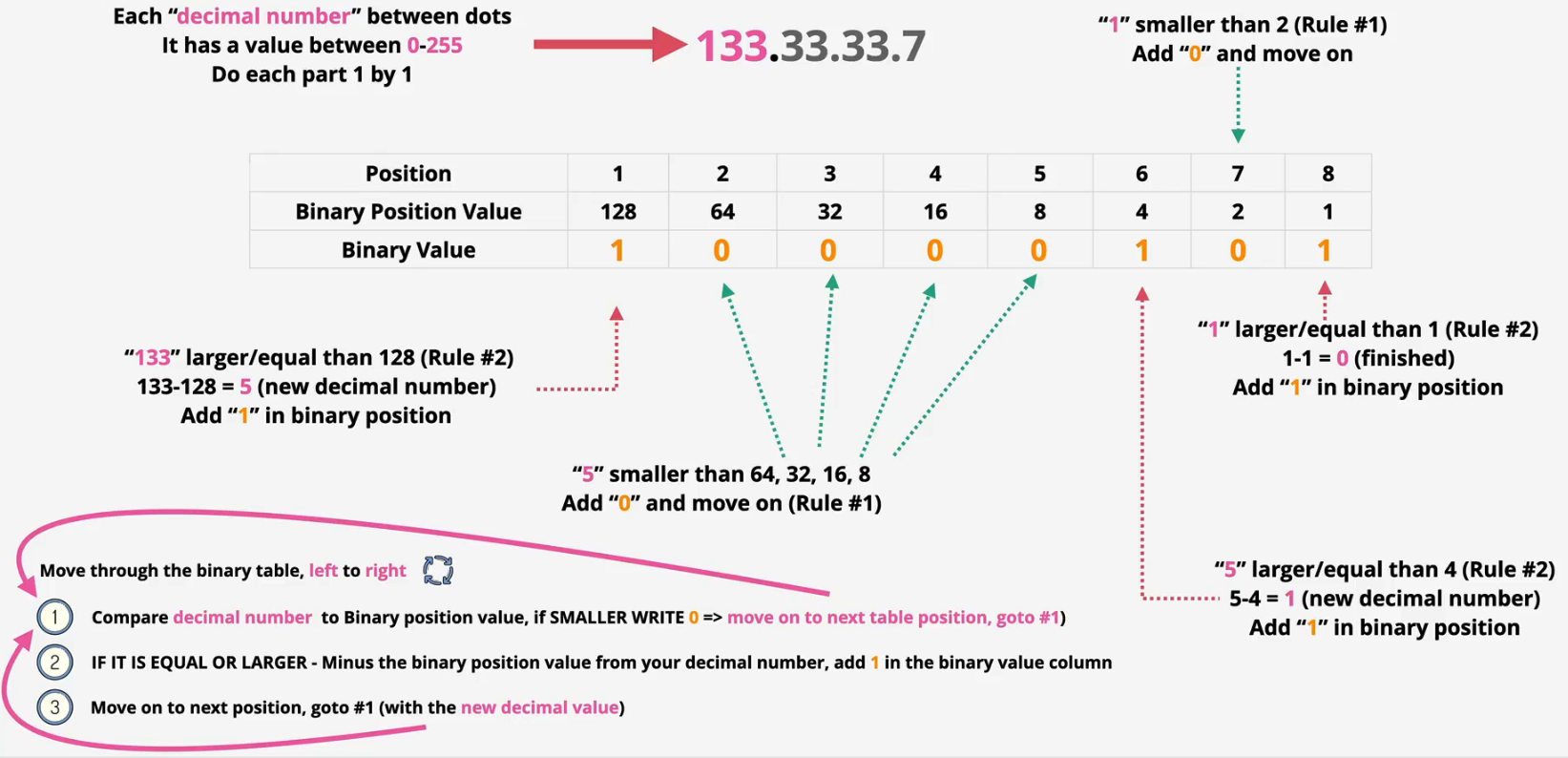
- Conversion: Decimal to binary
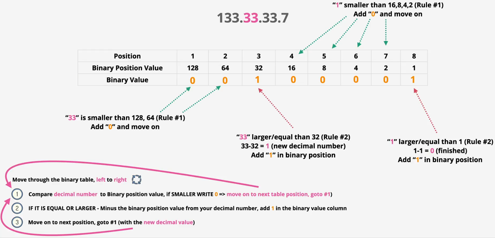
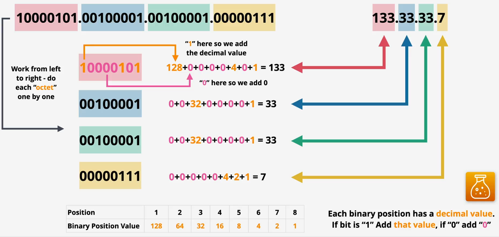
- Conversion: Binary to decimal
Layer 3
IPv4 and IPv6
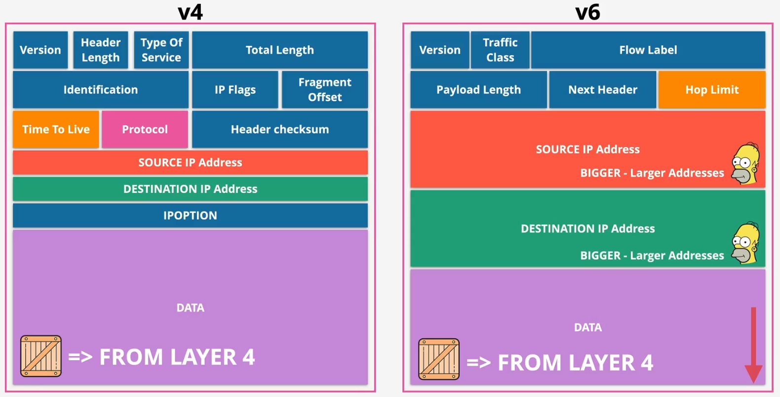
- IPv4
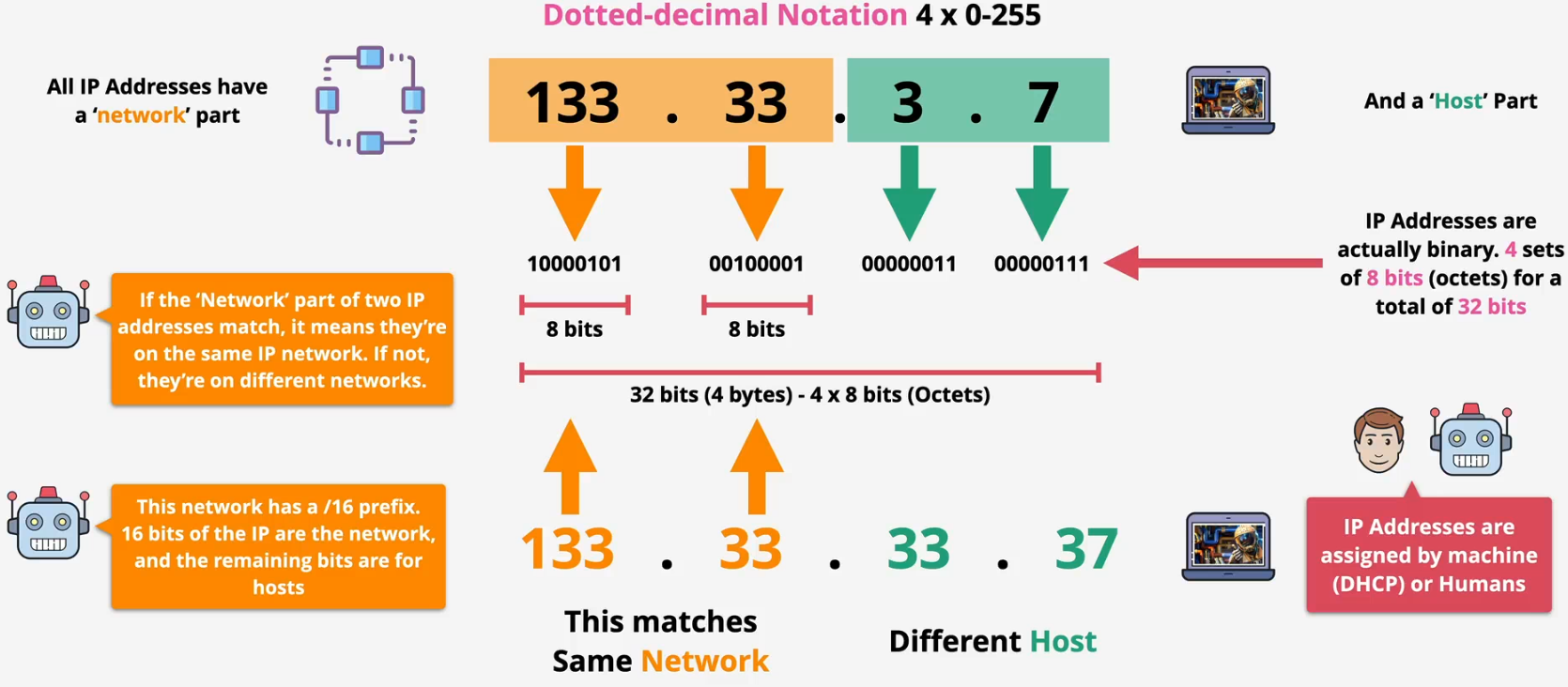
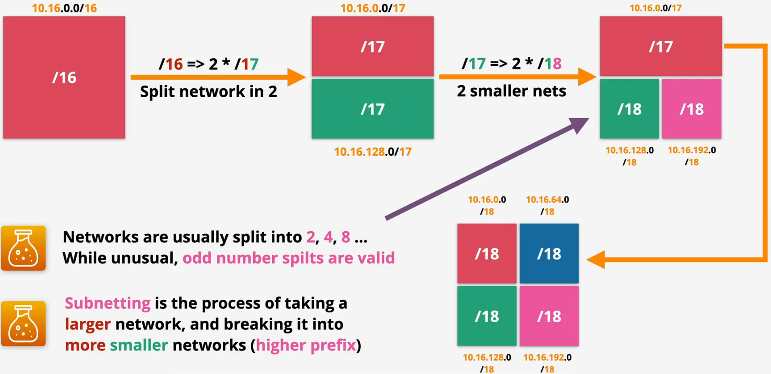
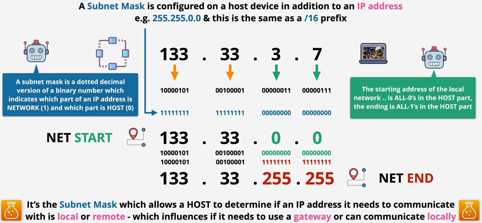
Subnet mask
- /16 in CIDR notation means the first 16 bits of an IP address are the network portion
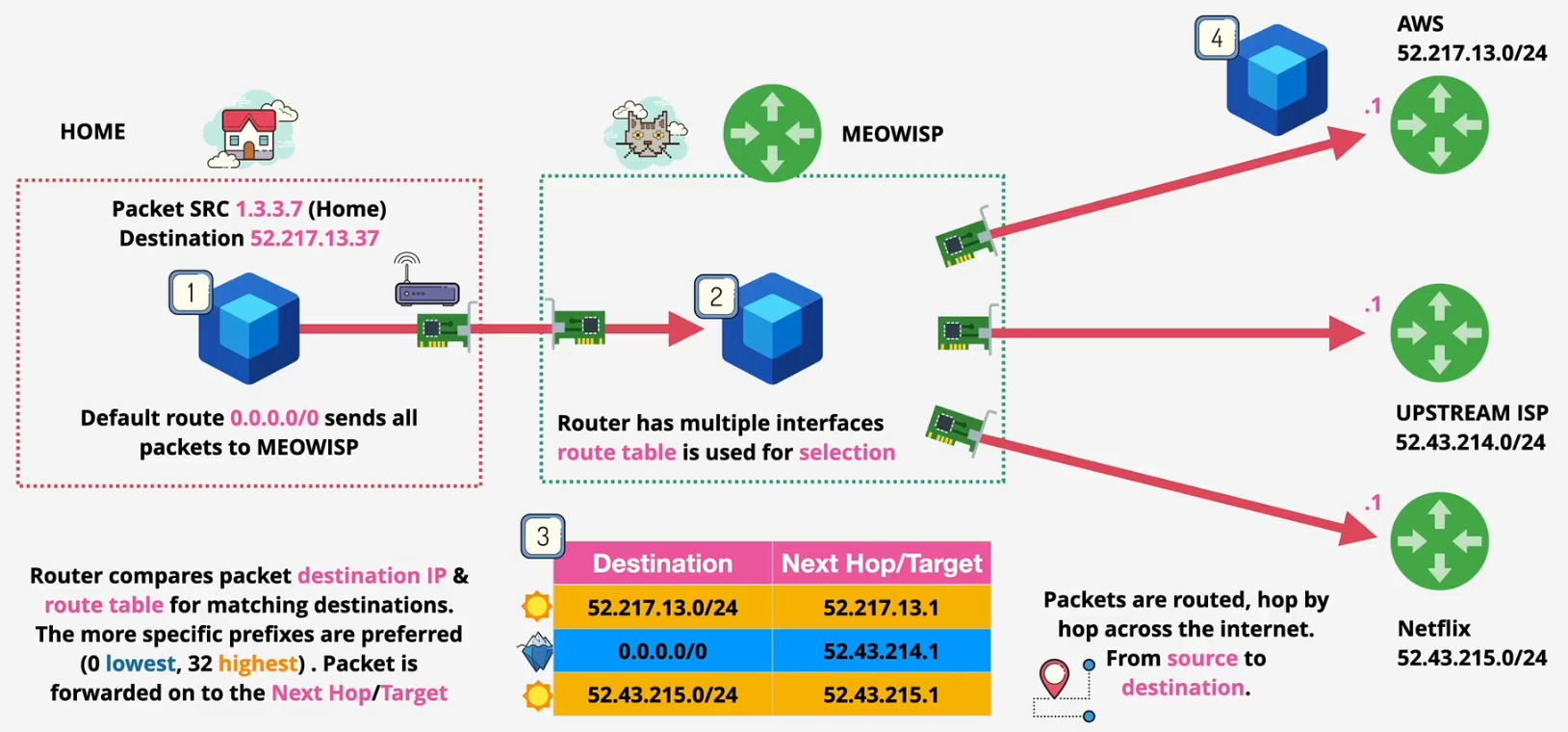
Route tables and routes
- Each router typically has a single routing table
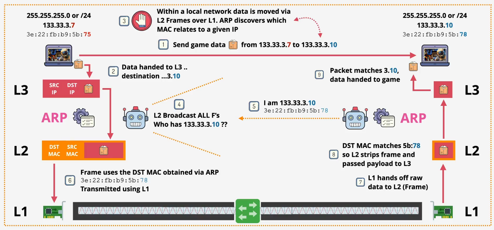
Address resolution protocol (ARP)
How routing works?
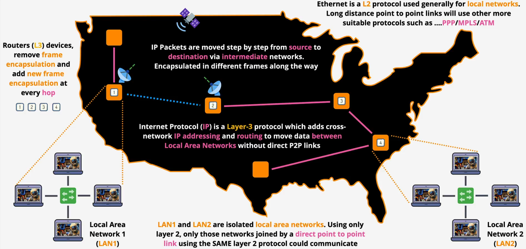
- During routing, the IP packet's core content (source/destination IP, payload) typically remains unchanged, but fields like TTL and checksum are modified
- Routers work at layer 3 but need MACs for layer 2
- MAC address is in frame header, not packet
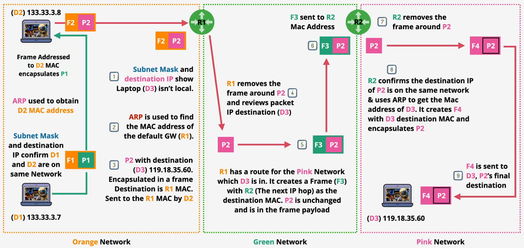
Summary
- IP addresses (IPv4/IPv6) enable cross-network addressing
- ARP maps an IP address to its corresponding MAC address
- A route determines where to forward a packet
- Routing tables store multiple routes for packet forwarding
- Routers move packets, encapsulated in Layer 2 frames
- Devices communicate over the Internet using IP addresses
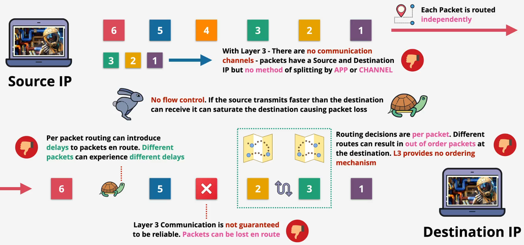
- IP uses source and destination IP addresses for communication
- IP packets may be delivered out of order
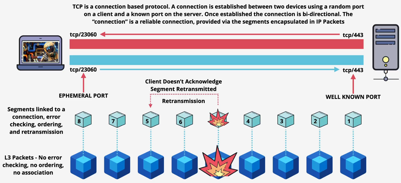
Layer 4 - Transport - Segment
Problems - Layer 3
TCP and UDP
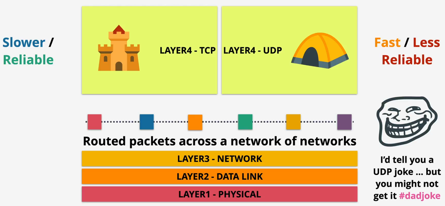
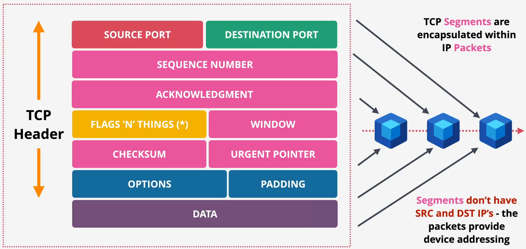
- TCP segments
- Source port: Identifies the port number of the sending application, enabling the recipient to know which application sent the data
- Destination port: Identifies the port number of the receiving application, allowing the recipient's operating system to direct the segment to the correct application
- Sequence number: A 32-bit number used to ensure correct ordering of data segments and to acknowledge received data
- Acknowledgment number: A 32-bit number used by the receiver to indicate the next sequence number it expects to receive, confirming receipt of previous segments
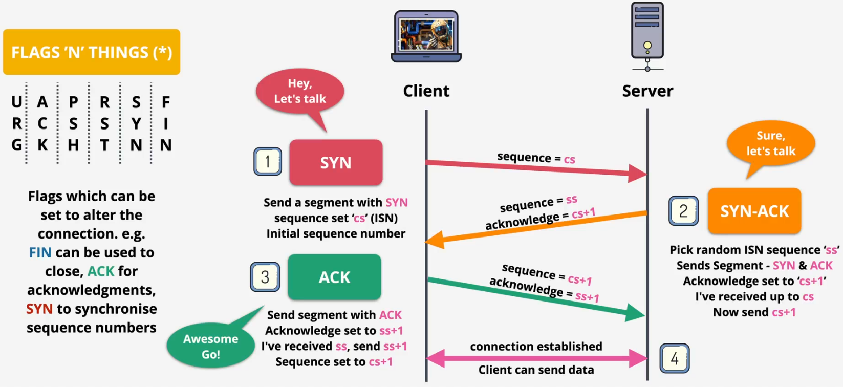
- Flags 'N' things (*): A set of 1-bit flags (e.g., SYN, ACK, FIN, RST, PSH, URG) that control the state and management of the TCP connection
- Window: A 16-bit field that specifies the number of data bytes the sender of this segment is willing to accept from the other end (flow control)
- Checksum: A 16-bit field used for error checking of the TCP header and data to ensure integrity
- Urgent pointer: A 16-bit field that, if the URG flag is set, indicates the offset from the current sequence number to the last byte of urgent data
- Options: A variable-length field used to convey additional information not covered in the standard header, such as Maximum Segment Size (MSS)
- Padding: Zero bits added to the end of the options field to ensure the TCP header ends on a 32-bit boundary
- TCP
Layer 5 - Session
TCP connection 3-way handshake
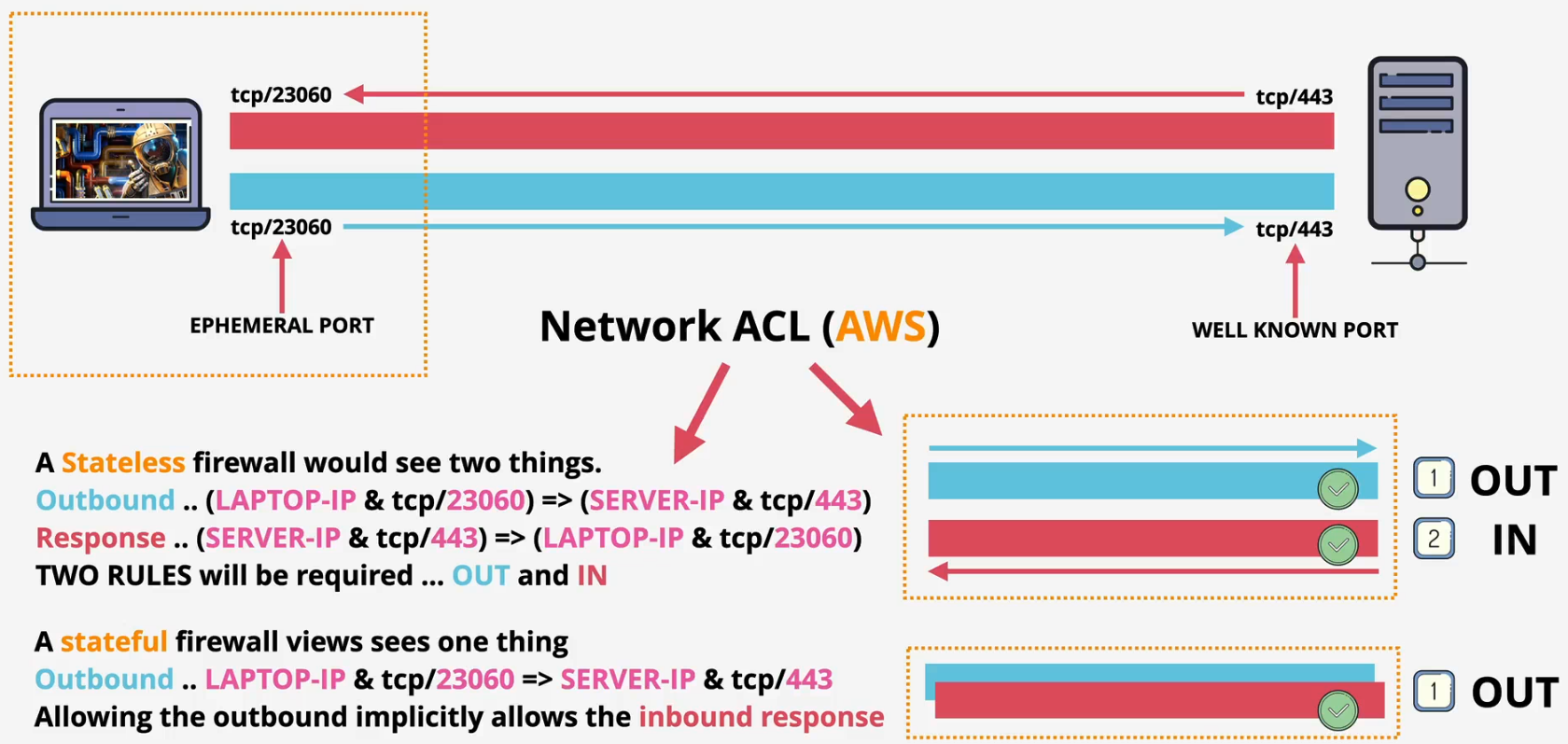
Session and state
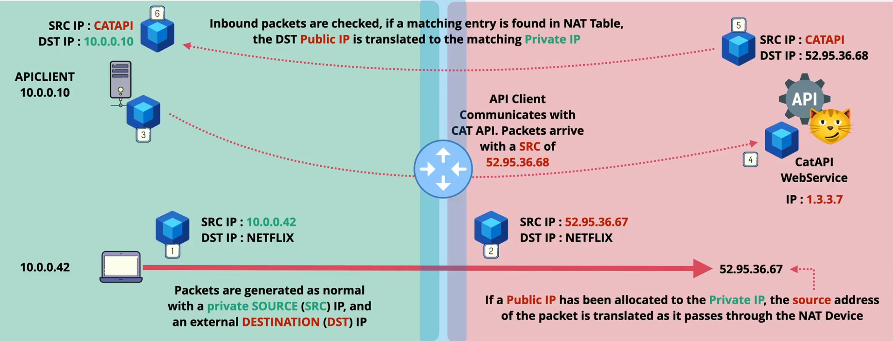
Network Address Translation (NAT)
- NAT is designed to overcome IPv4 shortages
- Provides some security benefits
- Translates private IPv4 addresses to public
- Static NAT - 1 private to 1 (fixed) public address (IGW)
- Dynamic NAT - 1 private to 1st available Public
- Port Address Translation (PAT) - many private to 1 public (NATGW)
- IPv4 only ... makes no sense with IPv6
Static
- The router (NAT Device) maintains a NAT table, it maps private IP : public IP (1:1)
- In AWS, this is how Internet Gateway (IGW) functions
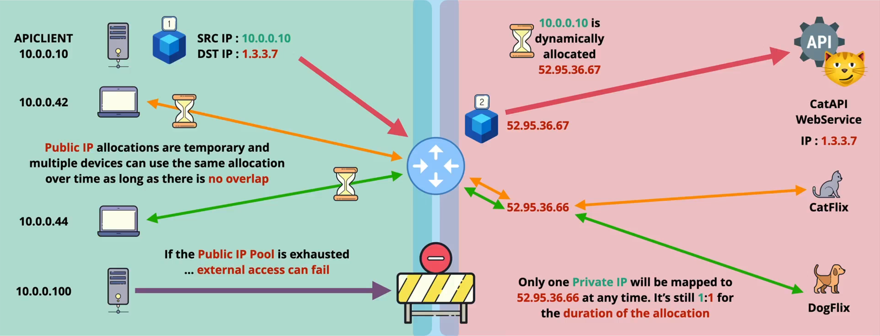
Dynamic
- The router (NAT Device) maintains a NAT table, it maps private IP : public IP
- Public IP allocations are temporary allocations from a public IP pool
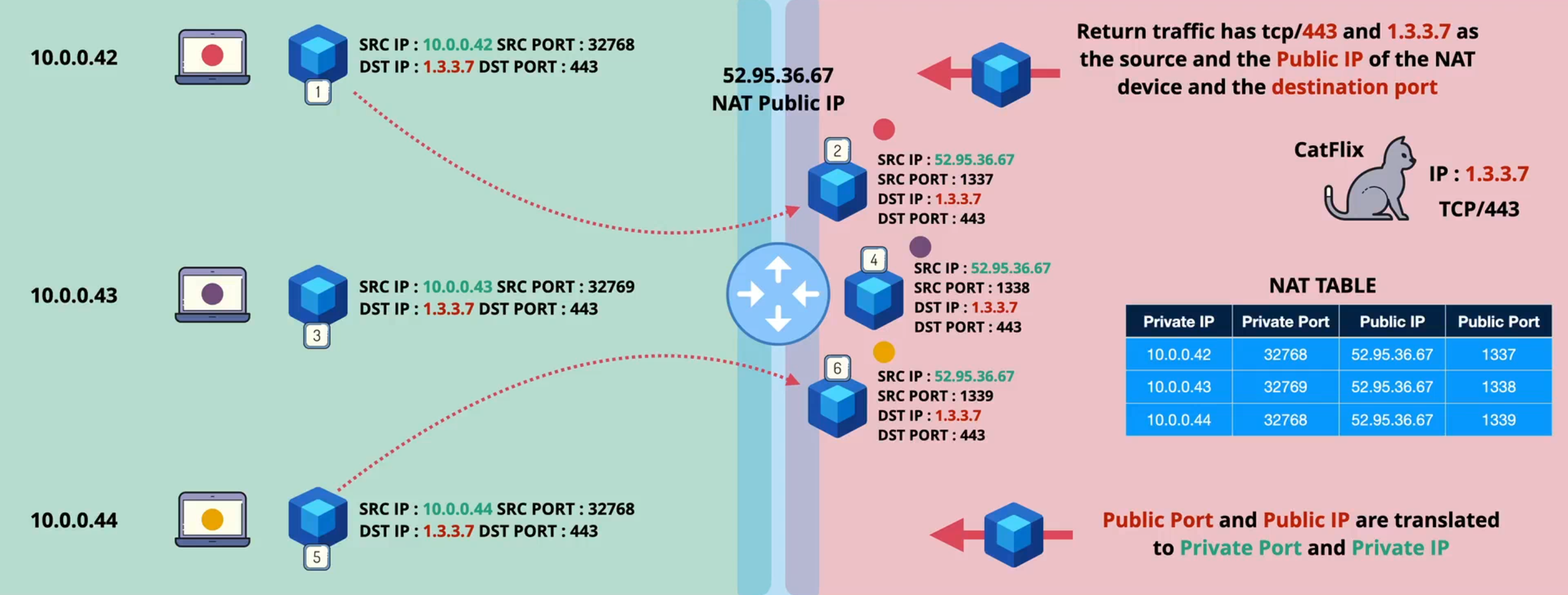
Port Address Translation (PAT)
- In AWS, this is how the NAT Gateway (NATGW) functions, a (many : 1) (private IP : public IP) architecture
- The NAT Device records the source - private IP and source port. It replaces the source IP with the single public IP and a public source port allocated from a pool which allows IP overloading (many to one)
Addressing
- IPv4 standard created in 1981, defined in RFC791
- 0.0.0.0 → 255.255.255.255 = 4,294,967,296 addresses
- Originally, directly managed by Internet Assigned Numbers Authority (IANA)
- Parts now delegated to regional authorities (ARIN, RIPE NCC, APNIC, LACNIC, AFRINIC)
- All public IPv4 addressing is allocated
- Part of the address space is private and can be used/reused freely
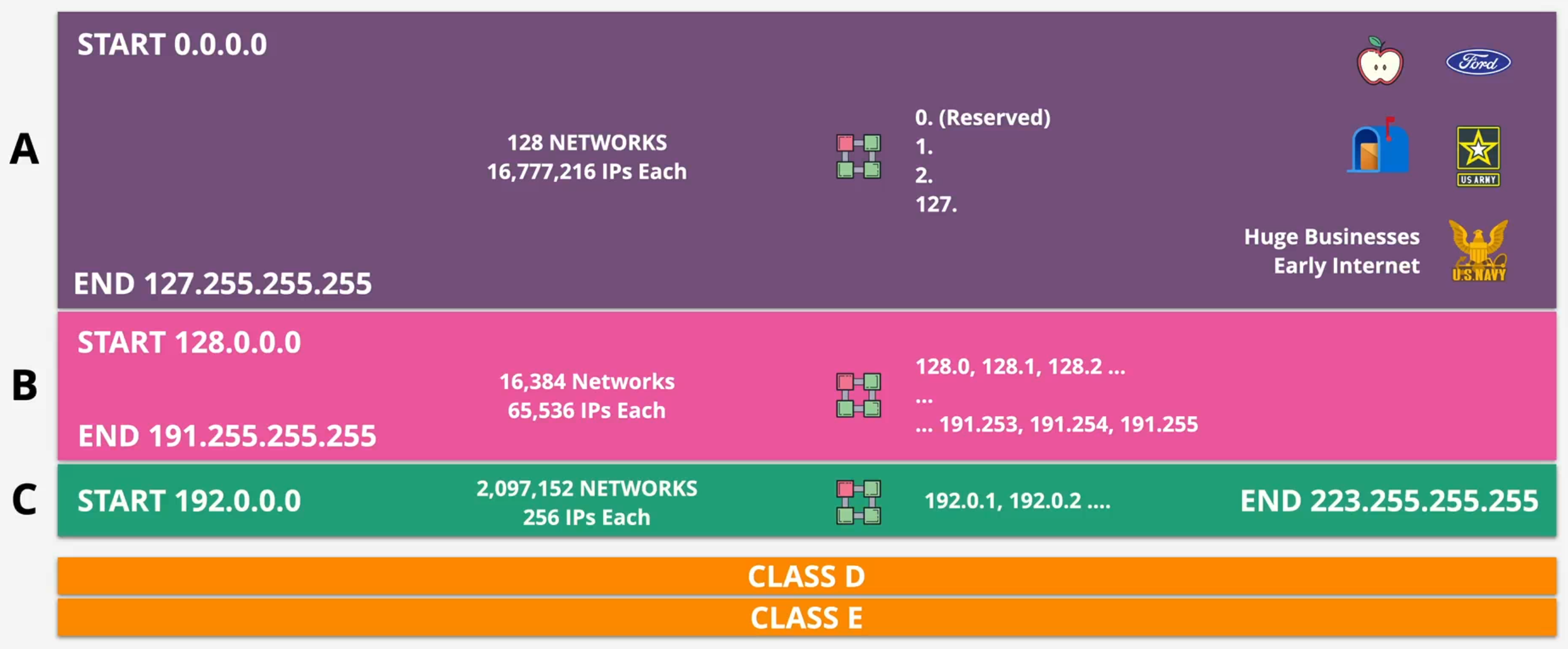
IPv4 Address Space
Private IPv4
- Defined by a standard RFC1918
- 10.0.0.0 - 10.255.255.255 (1 x Class A network)
- 16,777,216 IPV4 addresses
- 172.16.0.0 - 172.31.255.255 (16 x Class B networks)
- 16 x 65,536 IPV4 addresses
- 192.168.0.0 - 192.168.255.255 (256 x Class C networks)
- 256 × 256 IPv4 addresses
IPv6 Address Space
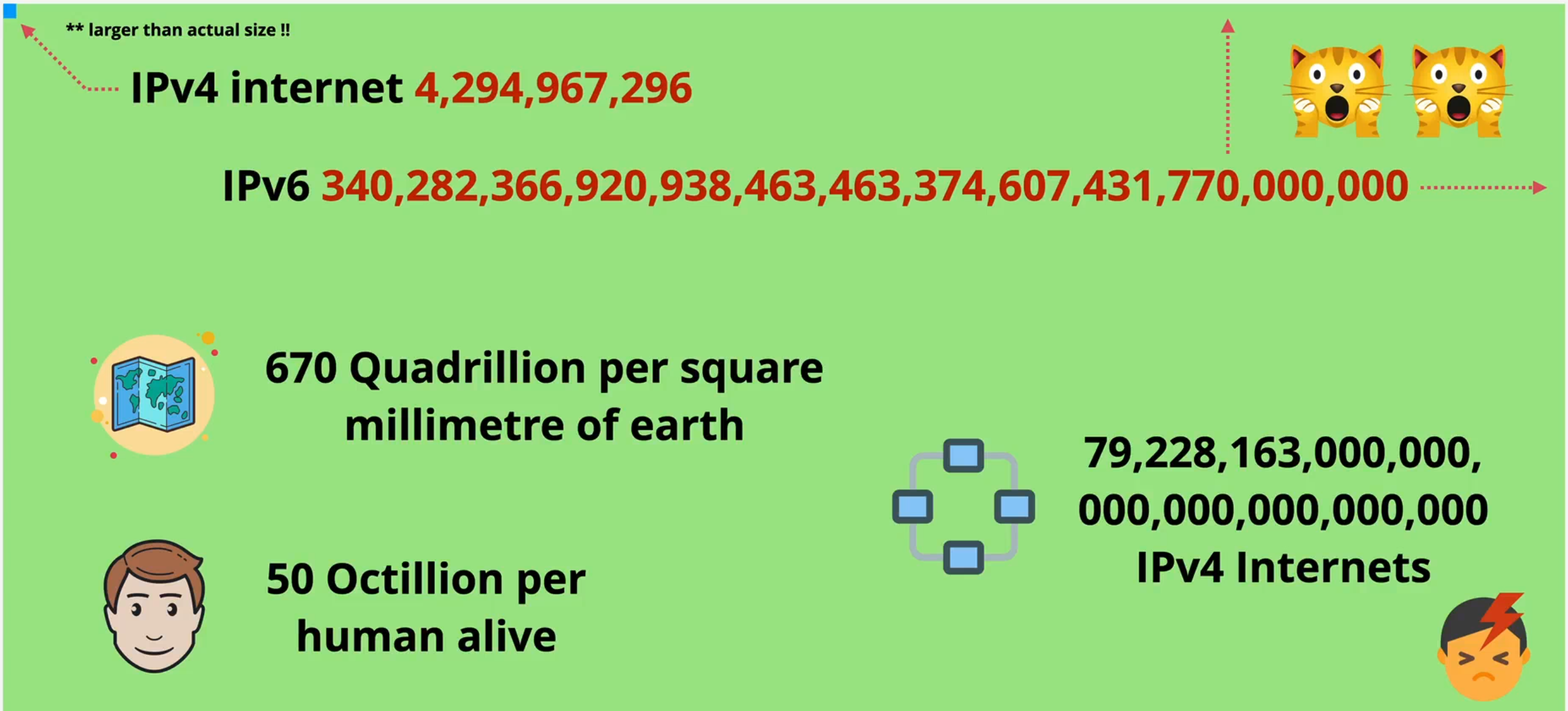
- Quadrillion: 1 followed by 15 zeros
- Octillion: 1 followed by 27 zeros
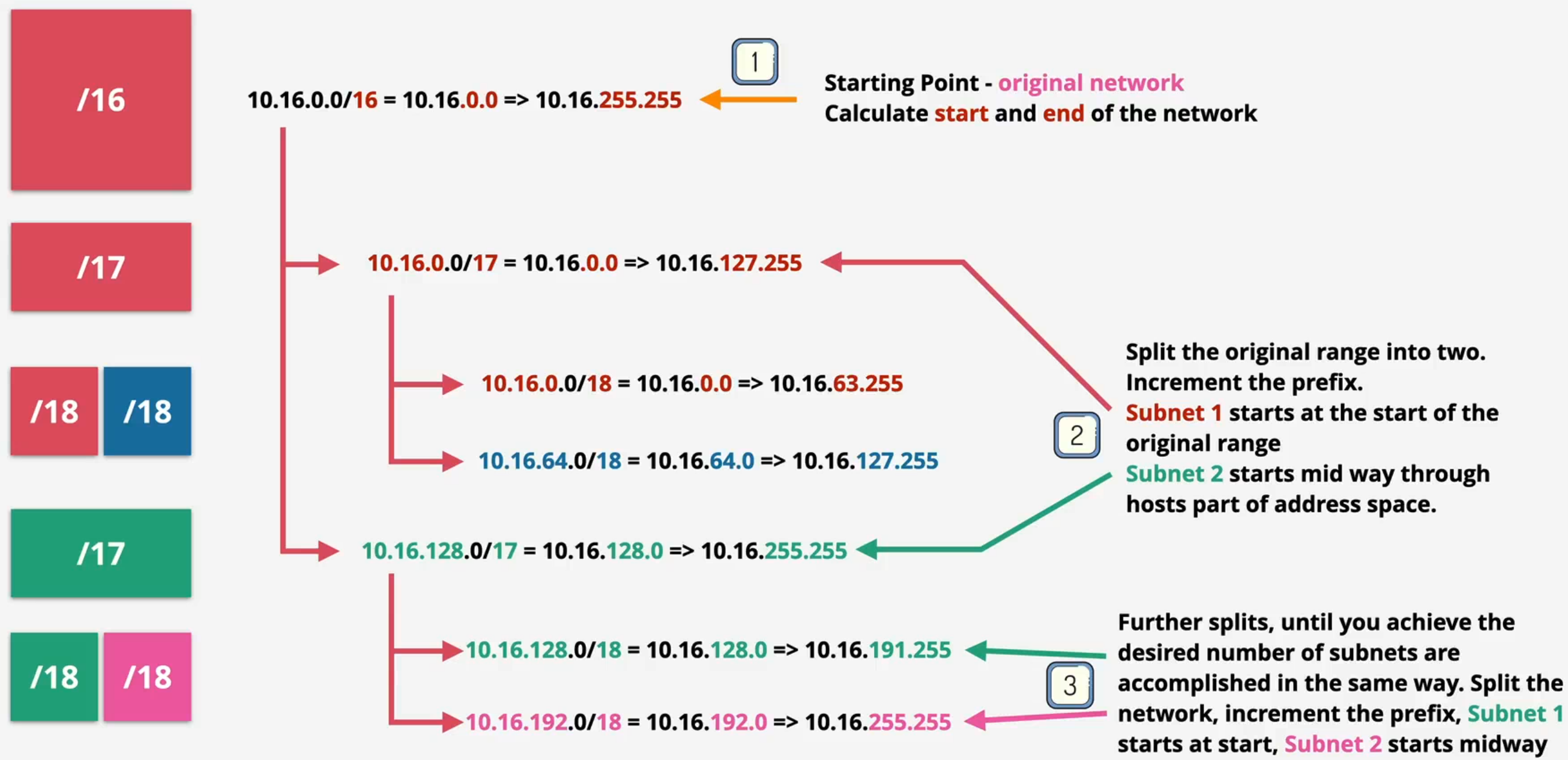
Subnetting